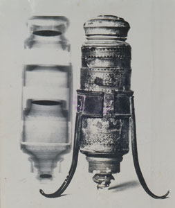
«In the X-RAY IMAGE are visible, from top to bottom, the protective cap on the eyepiece, the anterior chamber, the first eyepiece lens, and the mobile diaphragm. Continuing to observe the image, we find the second eyepiece lens mounted in a wood-and-cardboard cylinder that goes to rest in the seat provided by the nosepiece, and is removable. The distal section, in wood, which bears the objective, has three screw cylinders of different pitch; of these, the external one serves to mount the protective cap on the objective, the second to screw on the nosepiece spool, and the third to fix the last biconvex lens, between the two sections of the spool.»
« In the PHOTOGRAPH, on the larger cylinder of the tube can be seen the original inked marks traced to indicate the focal point. Visible above is the screw cap that protects the eyepiece, then a ring of decorated cardboard and, below it, a leather ring that serves as limit stop to the retractable cylinder and prevents contact between the mobile diaphragm and the part that supports the second eyepiece lens.»
« The support consists of an open ring with three legs, and its function as micrometer screw can be observed. One of the three legs, in fact, has a certain clearance on the nails fixing it to the ring, and is brought closer to the other leg as response to the maneuver of approaching the legs in order to widen the ring, allowing the tube to slide in it.»
F. Allodi, Descrizione di un microscopio, "Rivista di storia delle scienze mediche e naturali", Vol. XLVII, no. 2, July-December 1956.
|